Will 2.77:1 SWR harm my radio

I would like to use my Comet CX-333 tri-band antenna on GMRS as well if possible. I’m seeing 3:1 at 462MHz and 3.25:1 at 468MHz at the radio. The worst at the radio is just under 2.77:1 effective SWR with a 50ft run of IMR-400.

I would not be asking if it was <2.5 at the radio. I would not be asking if it were >3.0 at the radio. It’s in the middle and that is why I am asking.

I asked on Facebook and was told by an administrator that “no manufacturer will tell you the limit” and I needed “to get my house in order”. I was also told the question was answered when it was answered by general platitudes with no numbers or even general guidelines given. I figured this forum might be a little more reasonable than Facebook.

I’m currently using a Wouxon KG-1000G (older model–not the Plus) and a little birdy told me that the VGC VR-N7500 has a very wide mouth.

Assuming 40W and 50 ft of IMR-400 coax:

Comet CX-333 9.0 dBi gain (6.85 dBd):
Worst case SWR: 3.25:1
Matched Loss: Matched Loss: 1.37 dB, SWR Loss: 0.272 dB, Total Loss: 2.097dB (38%-15.2W)
Non-Transmitted Power: 15.2W
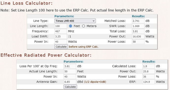
Effective Radiative Power (vs dipole): 124.9W

Browning BR-6157 4.5 dBd gain.
Worst case SWR: 1.658:1
Matched Loss: 1.37 dB, SWR Loss: 0.131 dB, Total Loss: 1.501 dB (29%-11.6W)
Effective Radiative Power (vs dipole): 80.4W

The ERP of the CX-333 is 55% higher (assuming the pattern is not wonky). The difference in frequency (a few percent) will probably de-optimize the colinear phasing a bit.

I think the issue is that you have fallen into the trap of quoting readings that have more decimal points than your equipment can probably measure. I’ve got 3 meters I use, and none of them read accurately. They give good indications, but they are not linear. The VSWR changes when I switch to higher powers, and it shouldn’t. 2.1 is better than 2.5 but my guess is that 2.5 is probably not 2.5 at all - but maybe 2.3 or 2.8? I had years ago an old Bird meter, and a few of the slugs. I regret selling it. The Thruline meters use the same components for forward and reverse measurements by rotating the slug 180 degrees - so the same measurement device with whatever deficiencies it has get used for both measurements, nulling them out. Other devices use two different rectifiers, so they can get out of alignment with each other. The usual problems with output stages with less than ideal VSWR is a balance of Power and the capability to deal with substantial power being reflected. Manufacturers never reveal the liklihood of reverse power damaging the output stage because it relates to time. Somebody who does short overs, or longer ones with longer gaps will be safer than somebody who presses the PTT and releases it ten minutes later. It’s so variable. I know that my own operating style is different on different bands. I chat for longer on ham bands, but much shorter transmissions on marine band. Business band, a bit further away still is probably the comms with the shortest transmissions. One of my antennas has very low VSWR on the ham bands. It rises to about 2.5 on the top end of marine and is over 3 at 169. No radio I have used over maybe 4 years on it has ever had a problem. However there is also a snag. As the VSWR rises, the antenna performs substantially worse, and the gain at 145MHz is pretty good. At 169MHz, I suspect the gain is less than a dipole. I wonder if the figures you have for those two antennas are correct? All the specs are for the resonant frequency are they not? When you say worst case VSWR, those losses will also increase, and the published gain figure will disappear? Very often I stick new antennas on an analyser and spot all kinds of strange peaks and troughs in the performance. A resonance at an unexpected frequency usually correlates with a similar dip in VSWR. Sometimes, my excitement that an antenna will be useful at that frequency just doesn’t work. I have a quad band antenns - 28/50/145/430, and discovered a nice dip at just over 70MHz - VSWR there was indicating under 2:1. It performed really poorly. A nice indicated match, good VSWR and a rubbish antenna. With higher output powers I also wonder if the VSWR is impacted by a measurable second harmonic - maths wise as they are related they should mirror each other, but I think they may not - so is my 2:1 reading really 2:1 at the transmit frequency, or is the reflected power at double the frequency messing the reading.

This, I think, is why nobody is willing to give you a firm opinion. 2.097dB is just 2dB - never describe with accuracy, something you cannot validate. I can tell you what I am happy with. 10W or less output power and I’d not worry about a 3:1 VSWR. Raise that to 25W, and I think my limit would be 2.5? I have a few rated at 65W and for me … 2:1 seems where experience makes me comfy. Not scientific, not evidenced by science. My experience tells me that at 3:1, it really means the antenna is going to be a poretty poor performer. Too long or too short, but 3:1 indicate a non-resonant antenna, so all published date is wrong. How much wrong varies between designs. A ¼ wave vertical on a decent ground plane has no gain, but a wide bandwidth. The bandwidth of the Comet is much tighter, and shift too far from the design frequency and it turns into a bit of metal in the sky. Height and decent feeder help of course, but switching to a resonant one ups signal level. On my 3 antenna mast on the office - the ham band antenna has 3dB of gain - but on marine, switching to the dedicated marine antenna with no gain, gives a just perceptable increase - I guess around 2dB better in listening terms. 12MHz up from 2m, and the 3dB gain has gone. VSWR is higher so that’s transmit power reduced too. I tend to use the ham band one on marine, because I only need local, and the radio is happy with the higher VSWR.

Your question just sort of asks for things people cannot answer, and they probably view your specifications with confusion. I can’t (for example) see where 80.4 Watts comes from? Or the 29%-11.6W bit? 40W output as RMS Watts is OK but matched loss, SWR loss and total loss confuse me - where do these figures come from, and at what frequency? You only want to know about 2.5 to 3 as a ratio? Sorry, but I am lost. So many specs and data statements but they make no sense to me as they don’t relate.

If you plot VSWR at gradually increasing frequency - you might get a far from straight line. Something causes it. non-lineality in the measuring circuit, odd new resonances impacting, and non-linear reduction in the gain, possibly with power throttle back as VSWR rises? I do not know how to isolate and measure this kind of thing. I do know that my meters, analyser with a bridge and a cheap network analyser all give me different readings and I cannot say which, if any, are telling the truth.

I don’t have time at work to answer all of your questions but I plan to. For now, I plan to test both antennas on two repeaters 80 and 50km away, ask for signal reports at a weekly net, and if available compare both antennas on a distant web SDR.

I know the difference between precision and accuracy but I also know about compounding error so I usually don’t reconcile the two to the same number of significant digits until the “management presentation” stage.

Matching loss is the direct loss from the coax. SWR loss is the additional loss from the reactive power oscillating between the radio and antenna making multiple transits of the coax. It’s not the reflected power that damages finals, as most of that power eventually gets dissipated by either radiation resistance or oh-mic resistance, it is the de-tuning of the finals that results in excess current within the finals. Because of that it is really the complex portion of the impedance that matters for stress on the finals. 2:1 SWR could mean 100 ohm antenna on a 50 ohm system or 25 ohm antenna on a 50 ohm system, and that is just the real part. It’s actually a circle on the Smith Chart that can result in 2:1.

My SWR measurements were done on a NanoVNA so I know the shape of the curve. The curve is a cursive W in the 70m hand band and very linear at GMRS frequencies (3.0 at 420 and 3.25 at 468). The curve is rock-steady when touching the coax ion the 70cm band and only moved a tiny bit when touching or even gripping the coax or base of the antenna in the GMRS band. I know there is a tiny amount of common mode current but from experience it is very small.

Effective Radiated Power (ERP) is the the power a dipole would need to generate the same signal in the direction of peak gain. (ERIP is usually used if comparing to in isotropic radiator). 100W ERP would mean a dipole in free space would have to radiate 100W in all direction to match the intensity in the direction of peak gain.

From modeling many HF antennas, my experience is SWR has only a tiny impact on far field pattern but I’m aware that is might effect the phasing with a collinear array. There is a 7% difference in wavelength between the center of the 70cm band and the top of the GMRS band? Will this completely collapse the constructive interference? My gut feeling is no.

I used the excellent loss calculator at KV5R.com to work up the numbers.

Sorry, new members can only embed one picture. Here is the ERP calculation.

You fell into the educator’s trap, and to be fair so did I. When answering questions, it’s vital to know the level of the questioner, and both of us assumed the listenership was perhaps a little less developed. I still don’t know what your results showing the losses with this degree of precision actually mean. I certainly do not have any test equipment capable of producing those results. In fact, I doubt any two reels of ‘identical’ cable will reach these levels of similarity. Certainly with many cable types being historically military specs, meeting the spec and labelling can mean two perform very differently. What really confuses me is the level of detail and precision in some areas mixed with untested or subjective input. Signal strength reports are pointless, unless you can do the evaluation. If the distant station sends you a recording of your antenna switching you can analyse it and measure the change in s/n. My local harbour authority constantly gets signal report requests. 99% are useless. Loud and Clear or Weak. These make me smile. Sometimes the signal is really strong, but the audio level low - a weak strength signal or a weak audio on a string signal. Other times people with severe interference from the ignition system, or charging system results with a loud and clear response. Coastguard are a bit better - weak but readable, or strong but unreadable due to wind noise - much more helpful. Hams with signal strength meters but repeaters might be able to put your test into words, but without a recording, who knows. A system that allows you to hear yourself back is the best you can hope for.

I almost accept the comments on the damage to finals - but struggle with the idea of measuring measuring to any sensible degree of accuracy reactive components. While back in college we had Smith Charts, I struggled with producing them with any kind of accuracy from the equipment at hand. The big, obvious elements were there but my understanding of what they actually were indicating was poor. Now they are one screen on my VNA, it’s a screen I still struggle with comprehending.

Your initial post indicated you were not as knowledgable as you clearly are - on many forums, they frown on asking er, less precise questions, hoping for at least a few detailed answers. Actually sometimes a good tactic to initiate a response. Here we don’t tend to get upset like, as you mentioned has happened elsewhere. The problem is I don’t think we can help. I certainly don’t have the Golden Fleece you are seeking. Not in education, or in equipment. I’m just a little stuck why you are researching Surely the only answer to the topic title ‘Will 2.77:1 SWR harm my radio?’ has to be ‘possibly’. My original comments still stand - power and length of transmission surely are absolutely critical, as is the design of the circuit. The big name bands usually make their hand-held business/professional products destruction proof because antenna misuse is so prevalent with the users. Other brands perhaps more popular with the budget conscious might not? All the precision and theory on one side of the equation set against unknown, unmeasured and variable components on the other. It’s a bit Don Quixote I think.

You are right that signal reports are no better than the person reporting but my thinking is that if I can access a Web SDR I can see my signal strength directly.

Updates:
SWR improved significantly putting the antenna on a mast. The Nano VNA is not a big enough counterpoise.

Meanwhile, I think I have found my solution.

  1. High SWR starts under 427MHz on the 70CM Band. Anything below $32 is slow scan TV. My regional frequency coordinator’s allocation starts at 440MHz and above. I never have to worry with an FM radio.
  2. If I want to use this antenna on GMRS, a Low-Pass Step-Down L (2.33 pF and 20nH) will keep it under 1.4 SWR across the entire band.