New and wonder, "How am I really going to link to a repeater?"

I have researched GMRS repeater information and location till I think I am blue in the face.

Taking the next step, I actually drove to two nearby repeaters and attempted to get on using all the information I had found about them pertaining to, RX frequency, TX frequency, PL codes like CTCSS/DCS, range coverage. Once I was inside the stated range, I pulled over and got my Midland MXT 400 and 6db gain antenna all set up and listed for the repeater ID.

I tried as best I could to get a reaction from the repeater(s) but to no avail. Eventually, driving as close to them as I could, they still stumped me and I returned confused. I must have been missing something, but what?

Well, one was actually off frequency the owner told me later thru an email. The other was totally off line. OK not to be beaten, I got all set up to try again in a month during an off road trip.

Hearing the repeater like it was next door I could still open the repeater with my radio signal. Sitting very high on a mountain top within 2 miles of the repeater still no satisfaction.
What I think I figured out, on the way home with my friend is that my setup just isn’t getting. As we traveled down differnt paths going away from each other the GMRS’s signal only lasted about three miles. Our CB radios remained better than the GMRS for almost two to three mile farther.

Bummer 40 watts out is just a little better than his handheld 1000V at 2 to 3 miles.

Point is you have to be able to get your signal to the repeater and just not be in the listed range of the repeater…
I’ve found there is such a thing as too much gain. I typically would always run regular 1/4 wave antenna because of this. Also, you could wait for years for some GMRS repeaters to ID (they aren’t required to like they are in amateur radio service).

What kind of terrain and where was the antenna mounted?

Mostly wooded areas and the terrain has been both from flat to hilly and mountainous.
I think the major issues are the repeaters themselves during my attempts. Having actually contacted the owners after the fact, I found out two were not (or possibly not) on line at the time even tho I could hear them ID.
Remember that I am trying to learn and understand how this all works in the real world and have only hit upon the private citizens efforts to provide this services.
The first two were located in SC. Hopkins and Alice Dr 575 (I don’t know how it either are mounted).
The third, RMPOA 550 is located in the mountains (near Brevard, NC) and mounted on a pole about 20’ up, as far I can remember. Owner stated later that the system might have been down temporarily due to some health issues.
All are listed in the Repeater section at MyGMRS site.

I am learning repeaters are living breathing systems that require private citizens and their funding and time to maintain them is for real. It must really be an endiver to operate and run these systems.

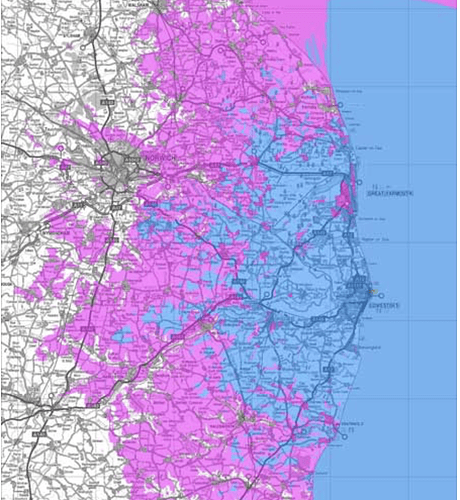
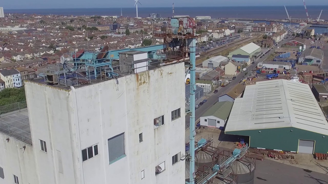
There is nothing magical about repeaters. The reality is that they have engineering and topographical compromises. Normally when you plan on a system to enable wide area comms you type in the location, the antenna height, antenna gain, system loss (throughs he feeder cables and filters) and the software people use which already has the local area topographical data in it produces a colour coded plan showing the likely service area. It’s NEVER a circle. This is the one from our ham repeater - mounted on a tall silo in the harbour about 200ft above ground. The blue area is where handhelds work fine, but in the pink area you need an antenna on a vehicle or your building. As for too much gain? Only if the way the gain is achieved is with a very low angle of radiation, which gets messed up if you go up or downhill and the most sensitive direction is into the sky or the ground. ¼ waves with the donut shape mean antenna orientation is n not so critical. It’s just physics.

Notice how the distance over the sea is really strong, yet as soon as it’s on land, attenuation rises quickly. You also have, about ten miles North of Lowestoft a pink area - this is where the land level is virtually at sea level, and the high ground all around makes it a repeater black spot. Here, we have no high ground, no big hills - it’s all pretty flat, but we still have poor reception areas from a very high site. Here’s a short video clip from the site - so you can see why it’s locally very good.

Repeaters are relatively simple devices. Simply a receiver and transmitter which are interconnected (think of it as the receive audio feeds the transmit audio). However, it can take some real skill and experience to troubleshoot various repeater issues and often requires test equipment that can easily one year’s worth of salary for the average Joe.

Paul’s first sentence about repeaters not being magical is actually quite funny as I posted a posting on my personal blog a few days back titled “Repeaters, Simple Witchcraft?”

1 Like

If you think getting started is a bit dark magic and sorcery, it’s nothing compared to turning a relatively ‘simple’ modular set of rack mount components that make up the repeater. Unless you’re a past master at solving EMC issues (and having an Rx and TX, let alone multiple sets of, on an antenna setup which is a compromise at best), nothing is that straightforward - EMC issues with the confines of the repeater itself just scratch the surface when you consider the field density locally at the site. And that’s talking about a single operator’s installation - when it’s multiple operators equipment sharing the site - put it this way, they haven’t created a painkiller that can fix those headaches.

Add in, from a user perspective and self-configuration of your end-user LMR set and demystifying a lot of conflicting versions of how to do, it’s no wonder that the only true painless setup of user equipment comes from buying preconfigure, which rarely is an option with ‘CB‘ type systems, you’re expected to just get out there and get knuckles dirty and get prematurely grey (a guaranteed scenario in the digital radio domain).

But, since I mention the digital domain, it’s amazing how few realize that with any digital transmission, too much signal is as bad as getting next to nothing like a really desperately below threshold signal is in the FM analog world. The thresholds in question which cover the range of SQ where you get a low error rate (which you want) are in a different league to analog FM (I say FM, as that’s what CB used here for modulation and most analog LMR services moved to it or later use digital voice FSK). When you get into anything FSK, the margin of threshold between a signal being useless weak and over threshold high is very narrow - ask anyone who worked with FSK type radio telegraphy before everything digital transmission became a kind of FSK.

Personally, I think half of all issues we have as end-users (the go it alone self setup ones) is a lot of half-assed how-to stuff we use as reference written by those who assume we’re all experts and often are too ■■■■ lazy to accommodate those lost in the wilderness, and that’s assuming the guide author/creator isn’t a victim of half-assed guides and sloth motivation.

Obviously, being in the UK I’m not familiar with the quirks and specifics of GMRS on a tech level or from experience, but like anything which has a digital aspect (even if the digital aspect is merely short message telegraphy or the user authentication/station I’d usage), you have to be configured right from the outset or you’ll be chasing your tails trying literally every combo of settings until you stumble on a working configuration and be no more the wiser for it.

I was part of a team who prototyped an early gen trunking system which had to coexist with existing analogue traffic back in the 80s, so I got a pretty hard ’kick in the dangly bits’ type sense of lost hope every time something went south on a direct course for the nearest sewer.

So I’m highly sympathetic of terminal confusion amongst self starters, and equally for the souls who have to maintain the gateways/repeater infrastructure. There’s no easy way anything will change until we lose and bury the secretive ’reveal to the worthy’ mindset so apparent out there in the radio comma world.

I’ll have to take ya word for it, as I didn’t understand a bit of it…

I admire the people who get trunking infrastructure up and running. That’s where the serious brainwork comes in. There’s loads of great repeater building stuff on the net, but we now expect far more from repeaters. In the past you’d get the most expensive filter setup you could afford and find that one person who could tune them the best. I’m ok at cavity tuning, but no matter how i adjust my order of tuning, a friend of mine always gets just that little extra rejection, and just a little less insertion loss,many often a steeper curve but flatter performance in the channel width at the tip of the notch. Even worse, they could do this before getting the fancy spectrum analyser and tracking generator.

All this said, using a repeater especially a marginal one is often down to technique. Squeezing the last erg out of the link.

I always thought trunking systems were fun to troubleshoot, build and deploy though pretty much all of my experience is with digital trunking systems such as Motorola’s Capacity Plus, Trident’s Connect Plus, Motorola’s Capacity Max (which is more hassle than it’s worth IMO), Simoco’s Xd Tier III offering, and Motorola’s Astro 25 (P25) systems. Been trying to find someone to finance me to build a vendor agnostic P25 system for a few years now but the opportunity hasn’t quite presented itself. That being said, it took quite some time for trunking to “click” and at some point that will be a topic on a blog post.

Tuning duplexer is a whole other story (the number of people who build repeaters but don’t know what desense is or how to test for it is quite amazing) and depending on the equipment being used to test and the cavity designs can be quite a pain (some duplexers I have to reference install documentation) and in worst case scenario’s they have to be broken apart into individual cavities and then retuned cavity by cavity just to get a good starting point. Cavity combiners are simple once you learn the easy way to tune them but preselectors can be a bear sometimes especially since some have a specific tuning method to follow. While I can tune some things the old fashioned way (fixed frequency gen and tuning for peak/trough) it’s much easier to do it with a tracking generator.

No question of doubt there, getting a system to just work (from design to functional in practice) is only a fraction of the story. As anyone vaguely experienced in radio knows, RF and proximity causes lots of headaches in the electronics and back then, we couldn’t use EMC modelling prediction software to simulate immunity, add in any number of environmental factors and human abuse, and you definitely have to commend and have respect for the engineers and infrastructure maintainers in general.

If it was easy, the maker world would be jumping all over the opportunity to make a. ‘open source’ repeater that was commercial grade as well.

@zap_p25 You mention fun about trunking systems. True, there can be a fun challenge to fault finding and the tech challenge as they evolve and mutate into ever complex variants (not always successfully). But from the other side of it , technically, they can be a total pig turning a concept design into a functioning proof of principle let alone serviceably complete.

I still have nightmares about it each time I try to reverse engineer the principle variations of a new design radio or obscure oldie. At least when I was up to my neck and in danger of drowning in design notes, the complex IC count was minimal and discrete modules meant daughter boards and a spaghetti junction of ridiculously necessary interconnects that defied belief.

■■■■, you could do that whole project, logic wise, these days on a couple of CPLD’s and a few ancillaries. It was when I first learnt to hate SMC construction and the fuelling fire never died out.

I was always quite pleased with my abilities to tune duplexers and filters ‘manually’ till I got an analyser with TG, and discovered none of my tunings were as accurate as I imagined. My repeater here never had as much range as I expected, but the service area was good enough. The notches were not as deep as they could have been and the analyser got me well over 10dB extra depth to the notches and steeper sides which helped the desense quite a bit. I also discovered that very often, tuning the VHF smaller size Chinese duplexers it was important to shift each cavity quite a way away, before walking each one into the right place. If they started too near, the interaction made getting the deepest notch more difficult.

Well, when you realise that a filter isn’t as centred as you thought, even though it apparent end result sounds OK, it’s amazing how much realisation you get from testing with a reference source.

In a receiver, you could just yank out a rubbish ceramic often found in domestic grade transceivers (CB and leisure grade LMR often, but mostly CB and toy WTs) and drop in a suitable narrow xtal replacement and see immediate selectively improvement, but sometimes you end up with edgy audio in the reception or a deaf receiver.

What you discover when you work with injecting a sig gen tuned output is how closely ‘centred’ the filter’s window actually is. And by a slight freq adjust on the gen, see how the filter is rejecting. A bit easier to do with an analyser, but an old school SIG gen and Mk 1 ears I find is pretty ■■■■ accurate.

Notably in the CB world, but not exclusively, people fail to compensate for the impedance mismatch of swooping out a fairly low impedence Ceramic item for a high impedance XTAL (which could be 10-20x higher). Just like in audio where severe mismatches shift tonal response windows, severe mismatches of an RF filter de-centers the filter’s relatively window (pass band) into an offset. Worse cause receiver deafness kicks in too.

So, in the pure analog and SIG gen world of setup, replacing resisters and caps in the same LC circuit section was necessary to correctly get the passband window true centred. A hour fine tuning with a SIG gen made a huge difference, and in some cases you discover some radios actually perform with a slightly narrower filter still at some clarity cost when selectively improvement matters more.

With the exception of RT spec DNT M and B40 rigs, which were factory fully optimised, I used 8khz xtal filters on CB rather than 10khz items, because the base selectively was so not fit for purpose, every bit of filter induced selectively helped. The price was that over-dev transmissions were awful to hear, but you learned to mentally ignore those.

By ear and MK1 brain based setup gets you in the ball park, but a SIG gen used right and in today’s world an analyser as well is where you need to be, especially given with DV modes, bandwidths are narrowing so filters being truly centred becomes more critical than ever.

And never forget, in seriously pro grade setups, they use cascaded filter modules, and those really do need proper setup from the outset, as the cascade’s composite attenuation increases the unit’s filtering by logarithmic substantial degrees when you composite a group of narrow and very narrow filters. It’s far more extreme than the resistor like series composite attenuation you get with inline use of cascaded attenuators.