We are setting up a remote PTT, remote speaker and remote mic for use with a Motorola DP2600.
We have the pinout for the 8 pin connector but we are unsure about the PTT circuit. We have stripped and tested an RSM and it appears to be pins 1 and 4 that are the PTT. We have measured 7K ohms when not pressed and 4.3K ohms when pressed across pins 1 and 4.
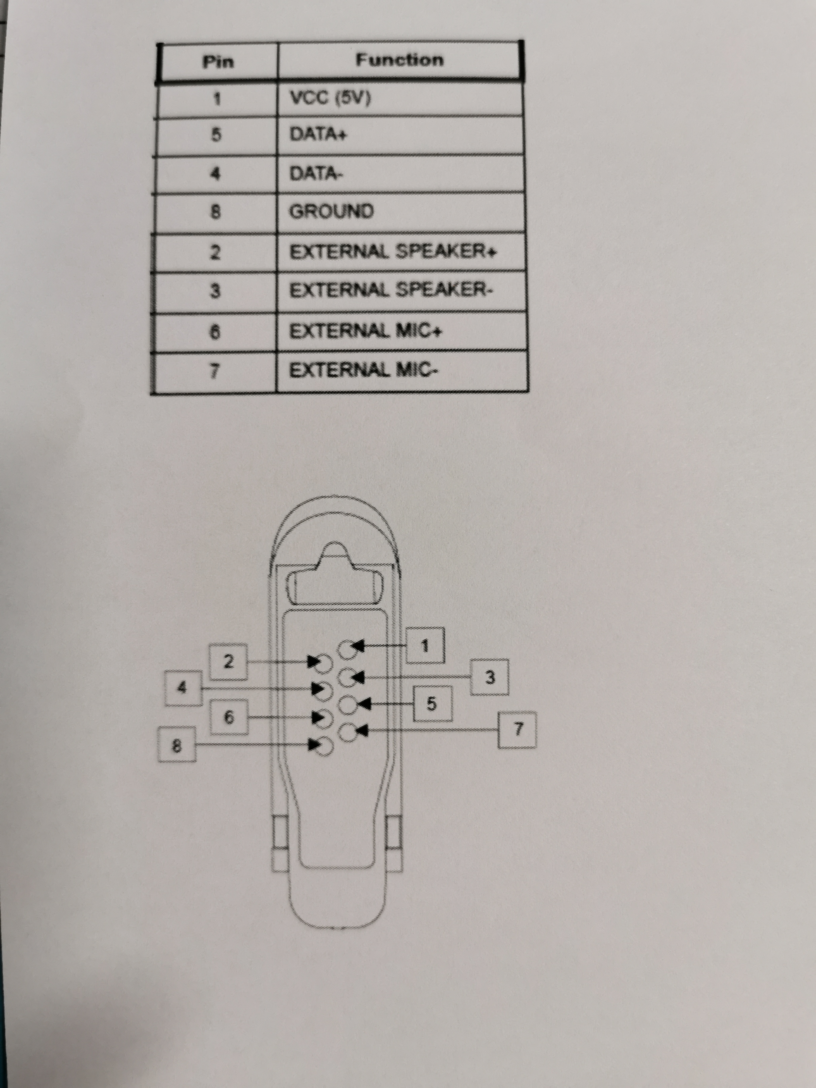
Are we on the correct path? Can anyone assist us by sharing a diagram for the correct setup of the PTT circuit for the DP2600? I have included a diagram of the side connector
It does look like you’re on the right path. But a suggestion is almost always to buy a cheap $10 earpiece to cut up and use a multi-meter. This is because there might be certain nuances like a resistor in the plug that the socket requires in order to allow the PTT to be activated for example.
Note that the DP2600 is the EMEA version of the XPR3500. So you can google both radios when doing your research.
Good luck.
Great advice, thanks
I had a TL in 5th SFG. He went on to do other things for the USG. Is it you??
This helped me out, for Data + and Data - , So Thank You.
But I believe the photo you attached is the Radio side connector and it is upside down (which confused me for a minute).!
Non specifically to any radio - when you see such a breakout and derived pin functions you can figure out that -
VCC, Data+, Data-, Ground are essentially the data exchange lines where it’s a serial/USB type programming or control cable normally used.
Now VCC could be providing phantom power for speaker/mic transducers, but typically where condensor/electret transducers are used, it’s more common to poke the phantom supply as DC up the audio lines (Speaker & Mic + it would appear on that breakout).
Most post-CB era gear and most professional/commercial gear used a simple PTT-Ground bridge to invoke the PTT (so essentially a short between PTT line and ground or the PTT- as that could be a discrete ground. Usually indicates the logic of the mode pin is pulled to one state and grounding it changes to a definite opposite state either way vs a floating indefinite state)
So it’s likely based on that breakout, each side of the speaker element/TD connects to a SPK connection, PTT switch connects between the PTT lines.
A simple test is to carefully bridge PTT+ to GND or PTT+ to PTT-. One of those should trigger the PTT state and send an effectively empty carrier. You may want to add a resistor in line or parallel when testing. But I’d be inclined to think the VCC/Data+/Data-/And is the comms/programming as (subject to voltage) that’s essentially the grouping you get on a USB port.
In fact, if you’ve got a programming cable that’s a basic USB data cable for it, you’ll probably find only the USB pins and those four connections radio side are actually used on the cable.
Where logic switching is used to trigger, and likewise for data transfer - 1.8V accidentally poked up a 3.3V level input does no damage, reverse combo isn’t advised. Ditto for 3.3V/5V and 5V poked up a 3.3V data line isn’t advisable.
5V sent up a 1.8v level input is a disaster/cooked pin port/chip replacement recipe that’s not enjoyable.
based in my experiment, the PTT pinout is a GND and DATA+
you can test by jumper the pin 8 and pin 5 recomend using resistor