Hi All, I ran into a strange issue that I’d like to throw out there and see if you’ve seen this before.
I built a dipole antenna for GMRS/FRS to attach to the house. I checked SWR and got it tuned to 1.01 I checked it on FRS and GMRS and had good readings. As soon as I went to any repeater channels, the SWR went up to 2.75! It does this on all repeater channels.
My radio is a Midland MXT275. So, to check to see what the heck was happening, I connected a Baofeng UV5R that is programmed to the same frequencies. Same result. Low SWR readings in the 1.01 range and as soon as I go to a repeater frequency, 2.75.
Any ideas would be appreciated
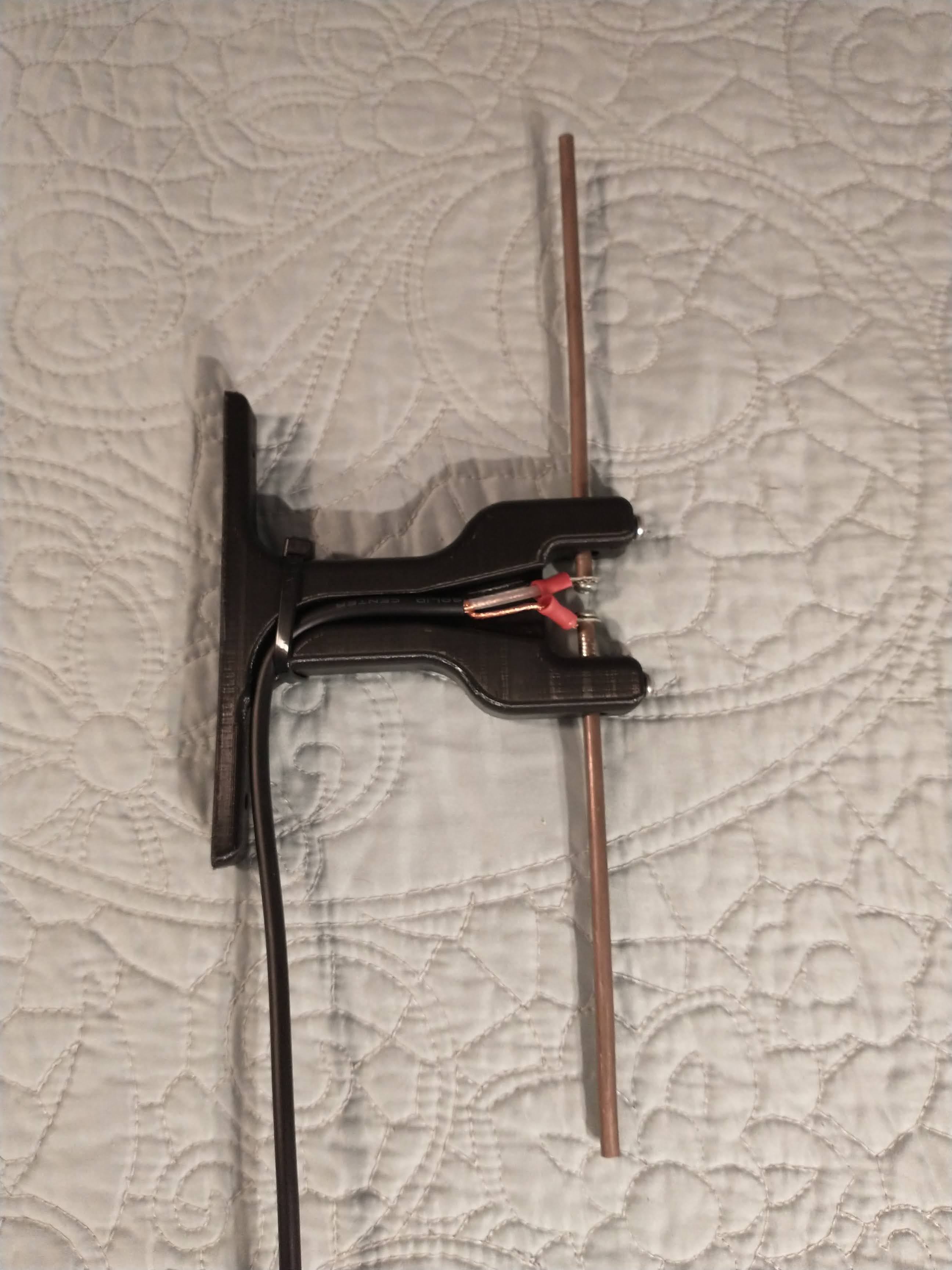
Photo of the antenna below. I used a 3D printer for the base.
Something is wrong, as dipoles have a very wide matching curve, so what you should do is draw out a list of the actual frequencies you are transmitting on, and starting with the lowest, draw a graph of frequency and VSWR. You should see a gentle curve as the frequency goes up. Ideally you cut the antenna so the best VSWR is in the centre, then it gets a little worse as you move away. With repeater channels, the frequency takes a jump away from the receive frequency, so tuning will be a bit off. Over 2 is quite a bit. So you may just have the lengths optimised for one end, and not the other. 5 MHz isnt very much really so I’m surprised the VSWR went up so much, so draw the curve based on the frequencies and see what it looks like. If the lowest frequency is best and the highest worst, then the elements are too long, so you can always nibble them a bit. I guess I’d be looking to get best performance at about 464/5 or there abouts. Let us know what your curve is. My guess is that your VSWR starts to rise immediately from the lowest channel and just goes up. The correct tuning would have it rising to 465 or so, then going down again, leaving highest and lowest at an acceptable VSWR
I just re-checked the Midland on low power and came up with 1.09 on the SWR.
I hadn’t checked it on low power because the Baofeng was only putting out a couple watts and I was getting the high reading with that radio too.
I’ll check a few more things and do some more trimming to see if I can get a good reading on high power.
Success! I took the plunge and started trimming again. I was able to tune it down to 1.03 on Channel 21R (462.700) SWR looks good across the board now.
I was reluctant to trim it down again because it’s a lot shorter than the calculators called for.
My final length is 10.5" total with each element at 5". The calculators were saying 6.025 for the elements with an overall length of 12.06. Well, I had a lot of trimming to do a 1/4" at a time.
It was quite picky about the length of the elements and how far apart they were but it’s all good now.
So, now I have something to hang out the window without disturbing my car antenna.
One thing. If your VSWR changes on high power, your meter is faulty. It measures a ratio between going out and coming back, so high and low power have the same ratio. You’re measurements also need to take the impedance into account. The real impedance of your antenna wont be 50 Ohms so the real maths to determine length is much more complicated. In most cases, you make them too long. Your tiny trims have made the match work, as indicated by the meter. Your meter may or may not be a good one, but there is only one worthwhile test. How does it work?
Seems to work okay. It’s not too busy around here to try a chat but I’ve triggered a repeater that’s 38 miles away in the mountains. That was with a height of about 8’ @ 15 watts. I’ll have more time to monitor traffic over the next few days. Our local repeater just came back online so I’ll be trying that one. It’s only about 5 miles though.
Follow up question. Does amount of wire that’s separated at the end of the coax for attaching to the antenna add to the element length? I do have about 1-1/4" of stripped wire. That would add up to just about right for the total length calculated.
In your case, yes it does, but the closeness tends to prevent that bit doing much for performance. The maths is a bit tricky because your radio expects 50ohm impedance, the cable is 50, but dipoles are higher, just over 70. Then you have your transition, where coax becomes two separate conductors. They’re also at right angles to the antenna plane. In a perfect world you’d use a balance on the end of the feeder to convert unbalanced to balanced, which a dipole is. The balun also sorts out the impedance shift. Commercial dipoles are usually folded dipoles. They go up, down, then back up, and have a higher impedance, that again the balun sorts out. In practical terms, for a receive only antenna I doubt you’d notice any difference, and bar some small changes to VSWR on transmit, the only thing for you to consider is performance and weatherproofing for outside use.
On my office mast I have an antenna for a vhf Maine plotter. It sends data bursts every few minutes. I found a cheap dipole, with adjustable telescopic ends. I stuck it on the meter, adjusted it for lowest VSWR and stuck it outside. I never bothered to measure it. I did stick the cable into my analyser a week or so later to see where it was resonant. Lowest VSWR at 162MHz, but the resonant frequency on the mast, with other antennas and poles is 2MHz lower. For my use, it doesn’t matter.