The best place, as always, to look is the data sheet or the installation instructions.
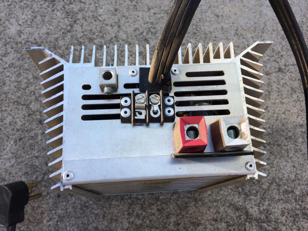
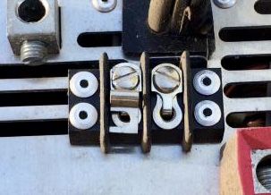
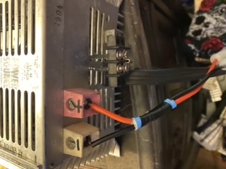
What you have, aside from the + & - terminals, is an extra chassis ground. It’s the ground connection you are finding a mystery.
When you also note what it was actually intended for, it makes a whole lot of sense, since it was built to be a charger/psu for an RV - the 30 model is one of a number in the series.
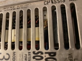
If it’s working ok, indoors, on + and - alone, leave well alone unless you really want to find a good earth to connect the ground connection to, but it’s a pointless exercise mostly since the Chassis Ground connection, like the battery negative on negative ground wiring, is connected to use the vehicle chassis as a negative return - so what you have is the means to chassis ground and/or use an isolated floating ground ‘negative’ and it’s that ‘floating not true ground’ you are probably using via the - terminal.
Now what i would exploit that for, is if i had kit with a discrete ground terminal on it, and had an accessible good ground indoors (even the mains ground here at my local isn’t so good, the rad pipes are actually better), i’d run a common braided or insulated chain of wire links between all your ground terminals on equipment, terminate it to ground where you can, and give everything an even common ground. But that’s me, it’s what i do with my audio kit and anything with a high-impedence input or output, and all the radios i ever owned had a ground terminal or had the breakout on the pcb for an unfitted part, so either way it got reinstated.
Helped no end, on an old HF rig, to have your common proper ground when working with a long wire.
It’s one of those things, not necessary usually on indoor installations where your mains plug has a ground pin and high load equipment usually (at least in the UK) has to be grounded at the mains, so the earth pin on the mains plug isn’t optional to wire up.
Given what it was intended for, mind, powering (mains tethered) and charging an RV battery bank, i’m hardly surprised it barely dips under Transmitter use - if i recall, it’s 30A Constant rated, so it’s peak rating will be safely 50% up on that, and at 30A, you can run most high power VHF/UHF mobiles quite well and the PSU will barely break a sweat. When you consider that car batteries (in old money) were around 45Ah rated, so you could technically get 45A off the battery from full charge for an hour under nominal temperature (remember, low (as in cold) temperatures alter the chemical process and inhibits delivery of full discharge current on a lead-acid just like with ni-cad and ni-mh cells and battery packs.
So a psu with a constant rating of 30A could take the load of a starter motor and a small-medium engine’s start-up turning, so driving a radio transceiver with up to 50W at the socket is comfortably within it’s potential. If it’s not a switch mode unit, it’s also delivering a very clean DC output as well as being overrated for what you are using it for, which i guess is the next best thing to a top grade PSU intended for the commercial market (like my old Pye PSU’s which were used for 25W mobiles by design and definitely predate the viral outbreak of common usage of SM PSU’s).
In fact, in the radio and in the world of sensitive ‘blow a substrate hole in a nanosecond under short circuit’ equipment, the only real piece of mind an SM unit gives is it has an almost instantaneous (faster than a fast blow fuse dies) shutdown under a short to ground condition or bad leakage to ground. Then, where the piece of mind is required, SM PSU’s make a lot of sense (unless you are talking HF radios, where SM PSU’s are as desirable as a powerline converter).