David - the problem is not the data, it is your context that is wrong. As I said, Decibels require a reference. The WW2 comment makes no sense at all. The facts are available in versions that use maths that school kids can understand and people with Phds have their own much more complex versions, but the upshot of a ½ wave dipole is that most gain claims have no basis in physics. Believe whatever you like, but the actual facts are very different from your current statements. I will leave it there as you are not receptive. Copper in concrete is a well understood concept, as is copper in earth. You could of course take any length of vertical radiator and mount it directly above an earth mat/ground plane but performance wise, all you are doing is increasing the capture area of a piece of metal as one component, and then going in and out of resonance depending on frequency. ¼ or ¾ would be different to the 1/2wave - typically the angle of maximum radiation is 20 to 30 degrees above horizontal. That is all that is happening.
It what read and noted
In late 1930’s they did a lot testing of FM too
That is a good point David - and the US was ahead of us in the move to FM. The Germans and the British never did the swap to FM during WW2 - I suppose, the risk and cost of a swap was low on the list back then. Historically, we used a network of radio hams across the UK to listen into German military and spy networks. At the start of the war, radios hams had their equipment confiscated, but many volunteered to work for the war effort by listening at pre-determined times and frequencies and transcribing what they hear - mainly Morse code. 5 figure groups of letters/numbers. These were collected locally and given to the codebreakers and other Government departments. Many of these volunteers remain ignorant of what they were even listening to, although many guessed. The radio history of WW2 here is considerable. Many of the wartime radios were still around, both British and American equipment, when I started in the 70’s.
I like that data
Greman’s are big on 11-meter too.
Germany is about 85% size of California
Dave
Here formula I found it watts in the calculations.
I do not know how good it is above 4 watts I have referred information to check it by only 11-meter 27mhz.
It is base on ½ wave tip at 8 or 10 meters or 267 to 33 feet monopole , J-Pole or dipole antenna. It also does not take for the terrain or weather In city the factor is 0.1 in rural 0.7 to 1 on ship in the ocean is 2 to 3.3 .
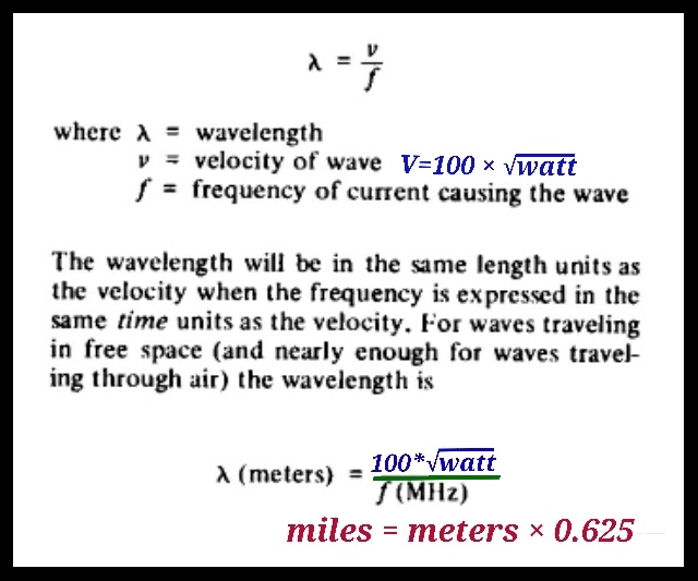
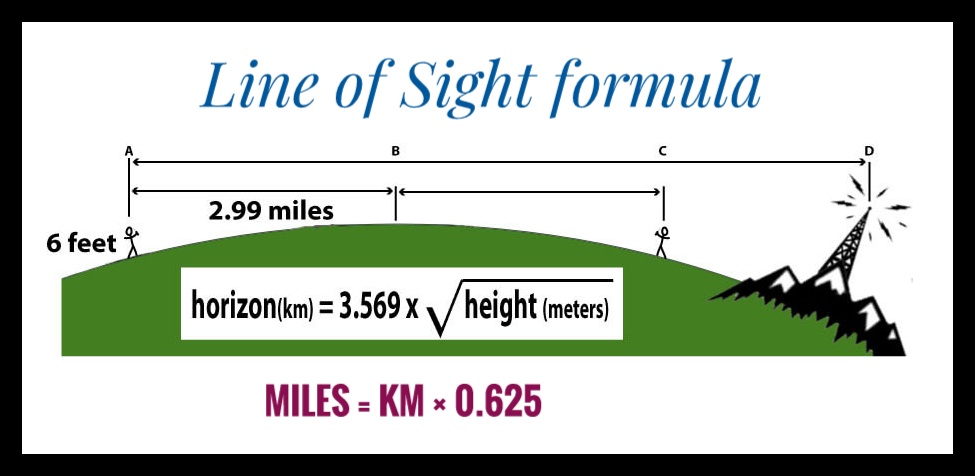
You also need to adding I line of sight
Here formula for LOS need the for both ends
Dave
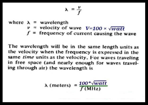
You might need to revisit the equation Dave. In metric, with velocity, as in the speed of light, in the top part of the fraction it works. 300 in the top box, with 150 for frequency in the bottom, produces 2 in the wavelength. This is is accurate enough, but it fails miserably if you try to use power in the equation. Frequency and wavelength do not change with Watts. The speed of light velocity cannot be swapped with power to change the wavelength. Never mess with mathematics. Either your source was an idiot, or somehow the formula got mangled somewhere and AI or a child misunderstood and posted it as fact. By replacing the component you are actually saying that the speed of light is 100 multiplied by the square root of the power in Watts. Very clearly that is impossible. Speed and power are not variable. Going to 100W from 10W does not change the speed of light, unless you are Dr Who.
I only report the data charts
Most data and formulas are from ARRL
Some have had color add in few cases I add the color to print.
My most reliable sources in the ARRL books. If go by internet is like the wild frontier of data. I even try duckduckAI it print this thread is good source of information. To me it us a good reason not to use AI .
What ever AI tried it like reading a box trying to sell something. I feel both of us want the correct answer. We both feed fairytale. From advertising or someone trying to be give opinions only.
Here more data from books on Ground Wave Propagation.
This a good paper for ground wave propagation
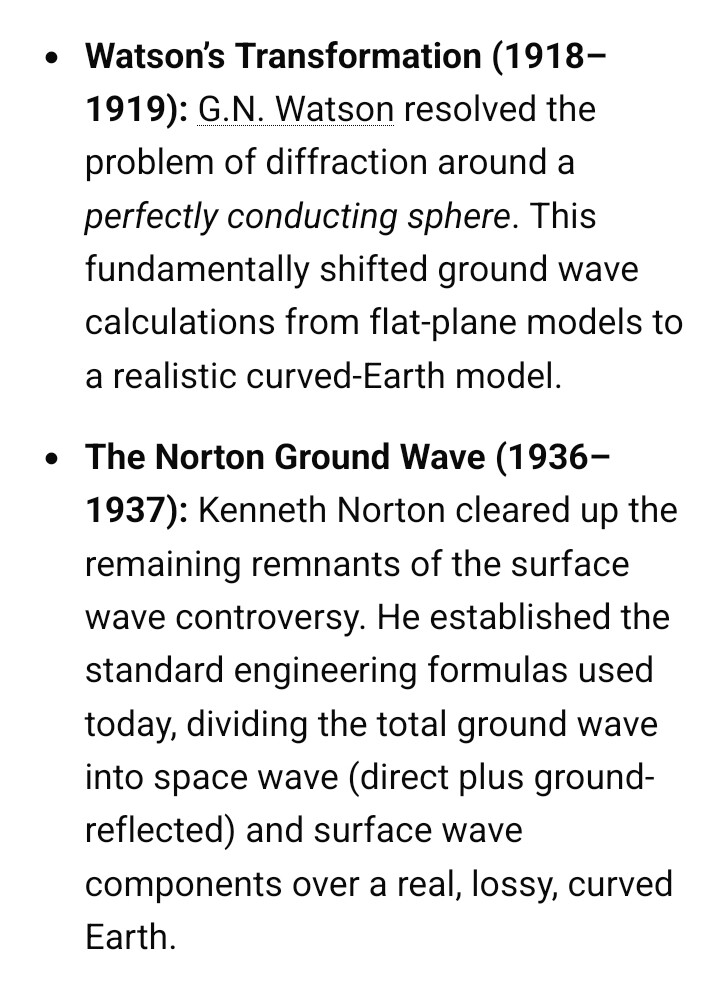
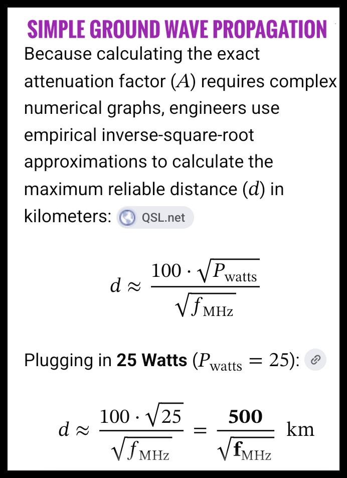
Here is how all formulas end with ≈
In my line work you could not use the symbol. All calcs had to be to 5th digits or greater. When start working most used was a sliderule it was to 3 digits Thank God for Excel
The symbol ≈ means “approximately equal to” or “almost equal to”. It is a mathematical symbol used to show that two expressions or values are very close to each other, but not exactly identical.
I found a lot written on this subject . There are more complex formulas but end they all with 20% on most day some will disagree. But even relies on each person ear too.
I like for antenna using the antenna I but not going over board
Dave
Here a good book too is more complex
https://www.itu.int/dms_pub/itu-r/opb/hdb/R-HDB-59-2014-PDF-E.pdf
Dave - you are mixing up different equations. V = 100 * SQ root of Watts, is the one to use if you want to know V (as in RF Volts in a loaded circuit - like 50Ohms, for example). You are also using V to indicate the velocity of the wave - as in the speed of light, less a bit. Every example you give to help people has not been thought through. Wavelength = velocity over frequency works if you specify the units as in metres or kilometres or Hertz vs MegaHertz. Precision simply has to be appropriate to the usage. Cutting a cable 50m long with an accuracy of 1.05mm is pointless. Making a little filter that has to resonate needs considerable measurement and cutting skill - so precision of measurement is relative. If you want people to understand, you have to be accurate. V is not the same as V. Volts and Velocity are quite different.